用TikZ的fit库实现插图标注 - registor
在使用插图时,往往需要对插图进行标,如添加说明、强调标记等。
用户通常会使用“绘图”、“Photoshop”、“GIMP”等工具通过图像编辑来实现插图标注。这是一种简单直接的方法,但这种方法会存在如下问题:
- 需要额外的软件支持,降低了文档的独立性
- 字体、字号无法与正文匹配,整体效果不协调
- 无法生成矢量注释文字,缩放会发生变形
- 不便于 LaTeX 文档后期修改、编辑和维护
笔者写过一篇用 tikz-imagelabels 宏包实现插图注解专栏文章,但使用 tikz-imagelabels 宏包进行标注时,只能在一个插图中进行标注,如果有多个插图需要统一标注,则这个宏包使用不太方便。
为此,可以在 LaTeX 中采用 TikZ 绘图工具,通过其 fit 库及绘图命令(主要是\node命令)实现标注。
载入 TikZ 宏包和扩展库
在文档导言区,载入 TikZ 宏包和必要的扩展库:
% 引入TikZ宏包
\usepackage{tikz}
% TikZ宏包扩展库
\usetikzlibrary{fit}% 坐标适配
\usetikzlibrary{positioning}% 坐标相对定位
\usetikzlibrary{calc}% 坐标计算
\usetikzlibrary{arrows.meta}% 箭头样式
定义辅助网格绘制命令
在进行图像标注时,为了能够快速定位,可以通过循环的方式,在需要标注的图像上绘制一个辅助网格,以提供坐标参考。为此,可以在导言区添加如下命令定义代码:
\newcommand{\drawgrid}{
  % 绘制辅助网络,坐标范围:(0, 0)--(1,1)
  \draw[very thin, draw=gray, step=0.02] (0,0) grid (1,1);
  \draw[thin, draw=red, xstep=0.1, ystep=0.1] (0,0) grid (1,1);
  \foreach \x in {0,1,...,9} {
    \node [anchor=north] at (\x/10,0) {\tiny 0.\x};
  }
  \node [anchor=north] at (1,0) {\tiny 1};

  \foreach \y in {0,1,...,9} {
    \node [anchor=east] at (0,\y/10) {\tiny 0.\y};
  }
    \node [anchor=east] at (0,1) {\tiny 1};
}%
为单幅插图添加标注
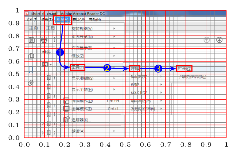
在 tikzpicture 环境中,用\node命令结合\includegraphics命令插入图像,注意将定位锚点设置在西南方向,也就是左下角位置。
用 scope 环境限定坐标区域为:x={(img1.south east)},y={(img1.north west)}。
用\node命令绘制命名矩形,可能在其可选参数中用 fit 指定绘制坐标,该坐标可以用绝对坐标,也可以通过坐标计算得到。
根据各个\node的名称,绘制表示关系的连线或其他标注。
为快速进行坐标定位,可以先用\drawgrid命令绘制辅助网格,然后根据辅助网格确定需要绘制的坐标值。
标注完整代码为:
\begin{tikzpicture}
  % 载入图像(注意定位锚点为西南,也就是左下角)
  \node[anchor=south west, inner sep=0](img1) at (0,0)
  {\includegraphics[width=0.85\textwidth]{02openreviewtools01}};

  % 限定坐标区域
  \begin{scope}[x={(img1.south east)},y={(img1.north west)}]
    % 绘制坐标辅助网络
    \drawgrid

    % 利用fit库绘制命名矩形
    \node[fit={(0.145,0.89) (0.235,0.96)}, inner sep=0pt, draw=red, thick] (view) {};
    \node[fit={(0.23,0.53) ($(0.23, 0.53) + (0.07, 0.045)$)}, inner sep=0pt, draw=red, thick] (tools) {};
    \node[fit={(0.522,0.52) ($(0.522, 0.52) + (0.05, 0.045)$)}, inner sep=0pt, draw=red, thick] (annotation) {};
    \node[fit={(0.755,0.52) ($(0.755, 0.52) + (0.075, 0.045)$)}, inner sep=0pt, draw=red, thick] (open) {};

    % 绘制箭头连线表示操作顺序(用node为连线添加标记)
    \draw[-{Stealth[scale=0.8]}, blue, thick] (view.south) to
    [out=-90, in=180] node[midway,circle,fill=blue,inner
    sep=0pt,minimum size=3pt,yellow] {\scriptsize \sffamily
      1}(tools.west); \draw[-{Stealth[scale=0.8]}, blue, thick]
    (tools.east) to [out=0, in=180]
    node[midway,circle,fill=blue,inner sep=0pt,minimum
    size=3pt,yellow] {\scriptsize \sffamily 2}(annotation.west);

    \draw[-{Stealth[scale=0.8]}, blue, thick] (annotation.east) to
    [out=0, in=180]node[midway,circle,fill=blue,inner
    sep=0pt,minimum size=3pt,yellow] {\scriptsize \sffamily 3}
    (open.west);
  \end{scope}
\end{tikzpicture}
其排版结果为:
为多幅插图添加标注
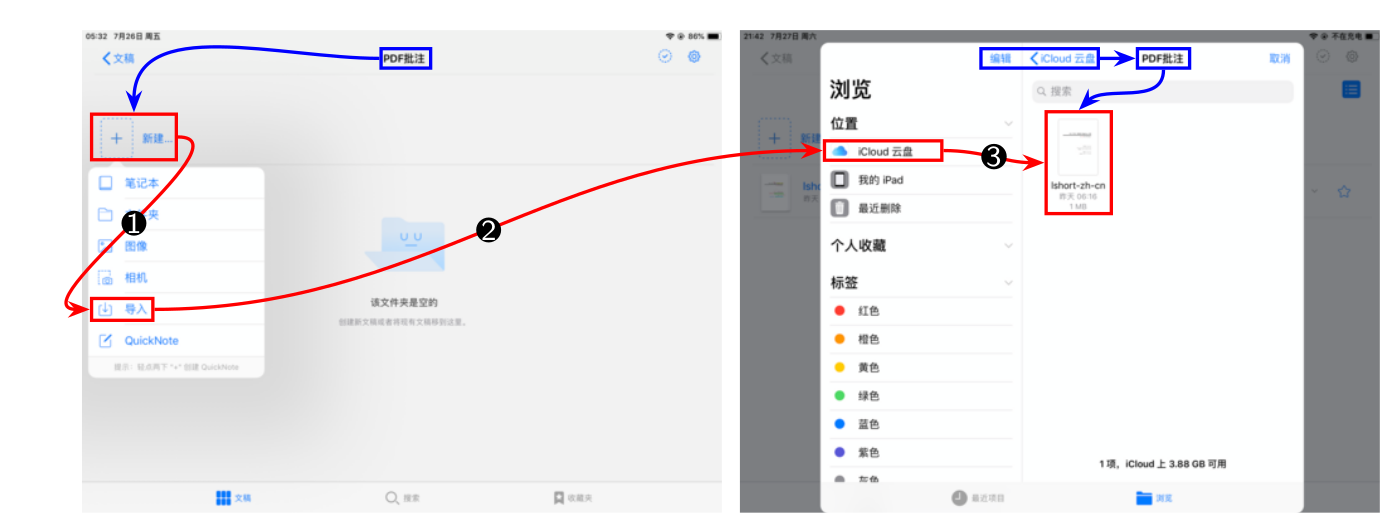
在 tikzpicture 环境中,用\node命令结合\includegraphics命令插入多幅图像,注意各个\node之间的相对关系及将各个\node的定位锚点设置在西南方向,也就是左下角位置。
用 scope 环境限定坐标区域为:x={(img2.south east)},y={(img1.north west)}(根据具体插图关系设置)。
用\node命令绘制命名矩形,可能在其可选参数中用fit指定绘制坐标,该坐标可以用绝对坐标,也可以通过坐标计算得到。
根据各个\node的名称,绘制表示关系的连线或其他标注。
为快速进行坐标定位,可以先用\drawgrid命令绘制辅助网格,然后根据辅助网格确定需要绘制的坐标值。
标注完整代码为:
\begin{tikzpicture}
  \node[anchor=south west, inner sep=0](img1) at (0,0)
  {\includegraphics[width=0.45\textwidth]{04importmenu}};
  \node[anchor=south west, inner sep=0, right=0.1 of img1](img2)
  {\includegraphics[width=0.45\textwidth]{05importicloud}};

  \begin{scope}[x={(img2.south east)},y={(img1.north west)}]
    % 绘制坐标辅助网络
    % \drawgrid

    % 利用fit库绘制命名矩形
    \node[fit={(0.23,0.92) (0.268, 0.96)}, inner sep=0pt, draw=blue, thick] (pdffold) {};
    \node[fit={(0.008,0.731) (0.073, 0.825)}, inner sep=0pt, draw=red, thick] (new) {};
    \node[fit={(0.008,0.4) (0.055, 0.445)}, inner sep=0pt, draw=red, thick] (import) {};
    \node[fit={(0.57,0.73) (0.66, 0.77)}, inner sep=0pt, draw=red, thick] (icloud) {};
    \node[fit={(0.69,0.92) (0.78, 0.96)}, inner sep=0pt, draw=blue, thick] (icloudroot) {};
    \node[fit={(0.81,0.92) (0.85, 0.96)}, inner sep=0pt, draw=blue, thick] (icloudpdf) {};
    \node[fit={(0.74,0.62) (0.79, 0.83)}, inner sep=0pt, draw=red, thick] (pdfname) {};

    % 绘制箭头连线表示操作顺序
    \draw[-{Stealth[scale=0.8]}, blue, thick] (pdffold.west) to
    [out=180, in=90] (new.north);

    \draw[-{Stealth[scale=0.8]}, red, thick] (new.east) to [out=0,
    in=180] node[midway,circle,fill=black,inner sep=0pt,minimum
    size=3pt,white] {\scriptsize \sffamily 1}(import.west);

    \draw[-{Stealth[scale=0.8]}, red, thick] (import.east) to
    [out=0, in=180] node[midway,circle,fill=black,inner
    sep=0pt,minimum size=3pt,white] {\scriptsize \sffamily
     2}(icloud.west);

    \draw[-{Stealth[scale=0.8]}, red, thick] (icloud.east) to
    [out=0, in=180]node[midway,circle,fill=black,inner
    sep=0pt,minimum size=3pt,white] {\scriptsize \sffamily 3} (pdfname.west);

    \draw[-{Stealth[scale=0.8]}, blue, thick] (icloudroot.east) to
    [out=0, in=180] (icloudpdf.west);

    \draw[-{Stealth[scale=0.8]}, blue, thick] (icloudpdf.south) to
    [out=-90, in=45] (pdfname.north);
  \end{scope}
\end{tikzpicture}
其排版结果为:
由于坐标采用了归一化处理,采用TikZ的fit库完成标注后,插图的缩放并不会影响标注的位置,这就为后续代码维护带来了极大的方便。
Happy TikZing!


