50 绘制围道时,处理均匀地添加曲线上的箭头的最佳实践?
发布于 2026-11-09 22:09:38
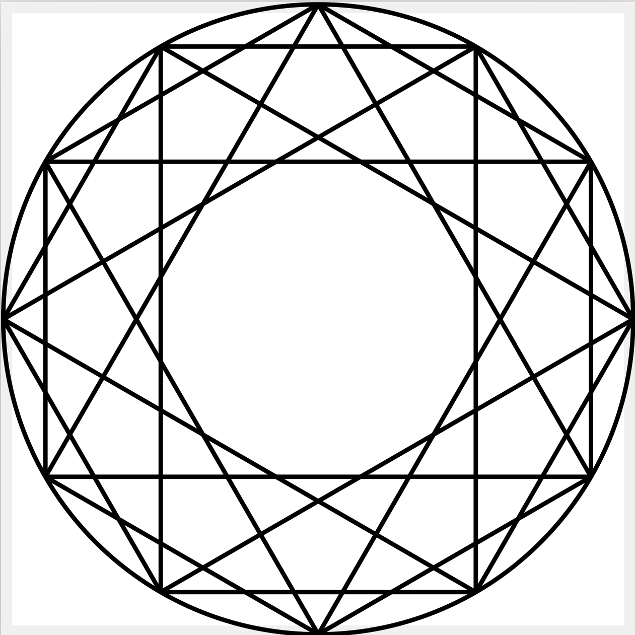
如题,考虑如下的目标:

可以先看下面的这份代码:
\documentclass[tikz,border=3.14pt]{standalone}
\usetikzlibrary{bending,decorations.markings,arrows.meta,calc}
\begin{document}
\begin{tikzpicture}[>={Kite[inset=0pt,length=0.28cm,bend]},
    decoration={markings,
        mark= at position .15 with {\arrow{>}},
        mark= at position .46 with {\arrow{>}},
        mark= at position .65 with {\arrow{>}},
        mark= at position .82 with {\arrow{>}},
    }]
    \def\eps{0.3}
    \def\bbeta{17.25}    % β = 2·arcsin(ε/2)
    \def\bhalf{8.63}     % β/2
    \filldraw[postaction={decorate}, thick, fill=gray!40]
        (-1+\eps, 0)
        -- (1-\eps, 0)
        arc (180:90+\bhalf:\eps)
        arc (\bbeta:90-\bbeta:1)
        arc (-\bhalf:-180+\bhalf:\eps)
        arc (90+\bbeta:180-\bbeta:1)
        arc (90-\bhalf:0:\eps)
        -- cycle;

    \draw[-Stealth] (-1.4, 0) -- (1.4, 0) node[below]{$\Re$};
    \draw[-Stealth] (0, -0.4) -- (0, 1.4) node[right]{$\Im$};
    \node[below left] at (0,0) {$O$};
    \fill ( 1, 0) circle (0.8pt);
    \fill (-1, 0) circle (0.8pt);
    \fill ( 0, 1) circle (0.8pt);
    \node[below] at ( 1, 0) {$(1,0)$};
    \node[below] at (-1, 0) {$(-1,0)$};
    \node[above] at ( 0, 1) {$(0,1)$};
\end{tikzpicture}

\end{document}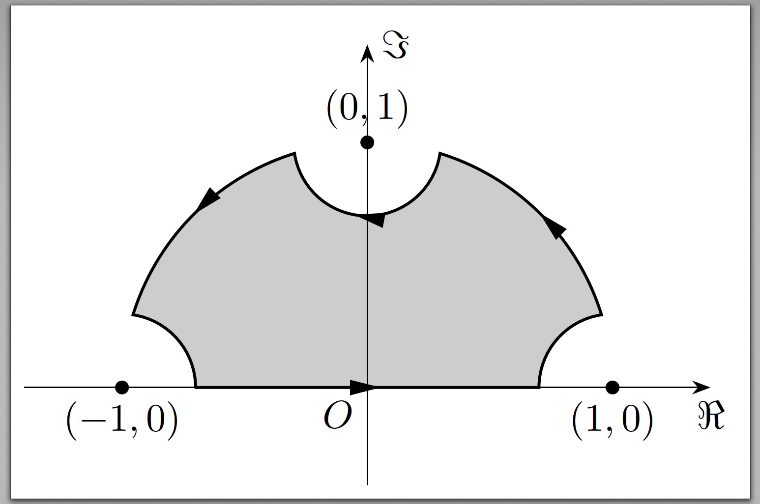
我大概有如下三个问题:
- 这里曲线上(尤其是曲率较大时)的箭头不是预期的
- 如何选择合适的多个比例来控制各个子路径“均匀”地分布在路径上
- 如果需要「既精确又灵活地控制放置四个箭头的位置」,此处的四个比例:
    decoration={markings,
        mark= at position .15 with {\arrow{>}},
        mark= at position .46 with {\arrow{>}},
        mark= at position .65 with {\arrow{>}},
        mark= at position .82 with {\arrow{>}},
    }]
可能需要经过数十次的反复编译以及调整! 这很不方便,希望在这里探求「最佳实践」;-)
关注者
1
被浏览
22