50 foreach在处理首尾相连问题时,「0,2,3,...,11」对于「11到0」的处理时如何避免特殊判断
发布于 2025-08-20 17:35:25
这个问题是上一个问题的姊妹版。
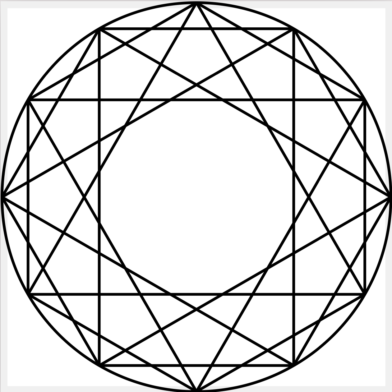
考虑如下首尾相连的情况:

下面的代码在处理边界「11->0」的时候进行的特判也并不优雅
\documentclass[border=10pt]{standalone}
\usepackage{tikz}
\begin{document}
  \begin{tikzpicture}[
    every label/.style={circle, inner sep=0pt, anchor=center}
  ]
    \foreach \i [
        count=\j from -1,
        % remember= \i as \ilast (initially 11)
    ] in {0,...,11} {
        \node[fill, circle, inner sep=1pt, label={
            [minimum width=2.5em,label distance=.2cm]{360/12*(\i-1/2)-60}:{\footnotesize $a_{\i}$}
        }] (a\i) at ({360/12*(\i-1/2)}:2) {};
        \ifnum\i=0\else
            \draw[latex-] (a\i) -- node[inner sep=0pt, circle] {} (a\j);
        \fi
    }
    \draw[latex-] (a0) -- node[inner sep=0pt, circle] {} (a11);
  \end{tikzpicture}
\end{document}
其中
\ifnum\i=0\else
    \draw[latex-] (a\i) -- node[inner sep=0pt, circle] {} (a\j);
\fi
和
\draw[latex-] (a0) -- node[inner sep=0pt, circle] {} (a11);同样让人觉得很呆。
尝试过
remember= \i as \ilast (initially 11)但在\i=0被处理时,\i=11并未被定义。
是否有技巧来避免这种ugly的特判呢?
可能有用
考虑如下坐标映射
x -> y
0 -> 1
1 -> 2
2 -> 3
3 -> 4
4 -> 5
5 -> 6
6 -> 7
7 -> 8
8 -> 9
9 -> 10
10 -> 11
11 -> 0
12 -> 1
13 -> 2
...
这可以通过:
\pgfmathtruncatemacro{\y}{mod(\x+1,12)}来计算...
关注者
0
被浏览
1.4k


感谢回复。
您上面的代码中用的是
这里的
(a\i)是node而(\angle-30:2)是coordinate!确实是不错的想法!非常感谢您!